Learning how to control an LED light strip with an ESP8266 microcontroller and WLED
I've been using a Raspberry Pi 3 B+ and Python to control an LED light strip for well over a year now. This was been part of an experimental, constantly-changing project that I've hinted at, but haven't gone public with.
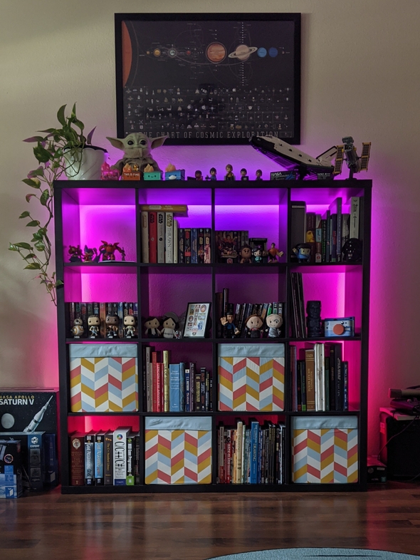
I can show you a nice picture of how they looked last September:
Unfortunately, something happened while I was trying to update some Rust binaries on the Pi over the weekend. Somehow, for some reason, my lights are dead.
I bought a new strip of LED lights, as well as three ESP8266 microcontrollers. I still plan on using the Raspberry Pi as the central controller for my lights, but my ultimate goal was to have multiple disconnected light strips synchronized via Wi-Fi.
Installing WLED on the ESP8266
While I liked tinkering with the Python script to control my lights, I'm looking for something a little more full-featured, and WLED seems to fit that bill.
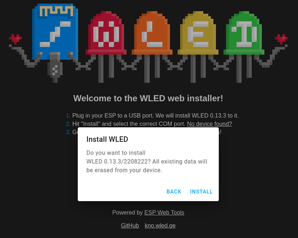
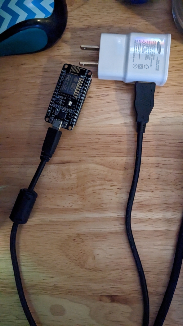
To get started, I plugged in the microcontroller to a USB port on my computer with a USB to micro USB cable. Opting for the easy install, I went to the web installer page.
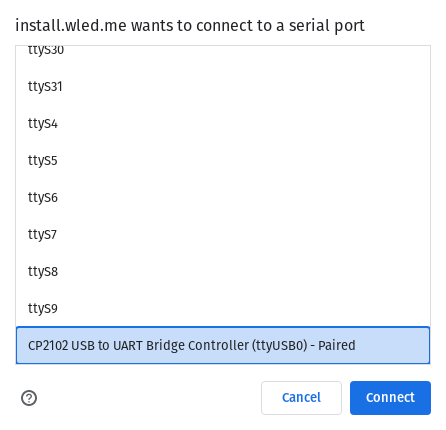
A bunch of ports popped up, but this particular one is the one I wanted, "CP2102 USB to UART Bridge Controller".
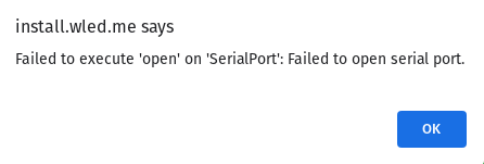
Unfortunately, I got an error message:
It turned out that I needed to add my user to the dialout group in order to use serial device ttyUSB0.
sudo usermod -a -G dialout maryThen, I had to log out and log back in again for the change to take effect.
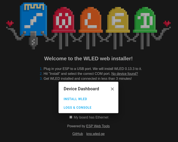
Finally, I had success.
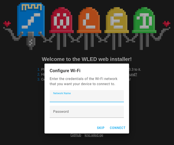
Once the installer is done, it'll ask for your Wi-Fi credentials.
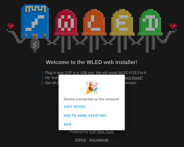
Once the device is connected to Wi-Fi, it'll ask you if you want to visit the device or add it to Home Assistant. How convenient! Unfortunately, I've recently decommissioned my Home Assistant because my tinkering rendered it, well, stupid.
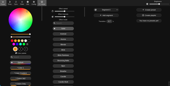
Clicking on "Visit device" led me to the device's IP address, and to a huge configuration screen for my lights.
Now I need to get some lights hooked up to this controller!
LED hookups
I've decided to power my LEDs through the Vin pin on the ESP8266, so all I needed to do to get power into the unit is to plug a USB to micro USB cable into a 5V power brick.
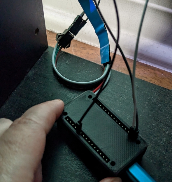
I've since added a 3D printed case to the controller, but in this picture you can see how I've used some female-to-male jump wires to connect the existing LED strip to the controller. It turned out that the old LEDs weren't burnt out after all. The black wire is connected to the Vin pin, the white wire next to it is connected to the GND pin, and the dark grey wire (which looks black in this picture but is alone on the other side of the board), is connected to the pin labeled D4. This is our data pin.
And with that, we have lights that are controllable with WLED!
