Quick and dirty fan hacking with a Raspberry Pi and a 433MHz transmitter
A few days ago I posted a bunch of links for a new project I had in mind. I want to remove as many remotes from my life as possible, and replace them with my phone. Eventually, I want to connect all of the smart devices and hacked smart devices together with something like Home Assistant. In order to do that, I needed some 433MHz transmitters, one of my unused Raspberry Pis, and some tutorials.
The components arrived at my house around 8:00 PM on Sunday. I only had a few hours to tinker with them before going to bed, and in the span of two hours, I had a shaky but working prototype for my office fan.
This is my first hardware hacking project, so I'm sure my terminology is going to be terrible, and I have no concept of best practices. Please bear with me 🐻.
Index
The components
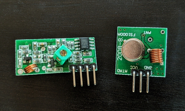
I got this 433MHz transmitter and receiver set from Amazon. I bought five pairs of receivers and transmitters for about $8. I kind of expected poor quality for so cheap, but the first ones I grabbed out of the box worked perfectly. The receiver module is on the left and the transmitter is on the right.
The prongs on the receiver, from left to right, are 5V power, two data outputs, and the ground (GND and VCC are printed on the back of the component). The transmitter has the data on the left, power in the middle, and the ground on the right. This Instructables tutorial has labeled pictures of each component.
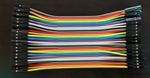
I also got a bunch of female-to-female jumper wires. A lot of tutorials I read used a breadboard to keep things cleaner, but I (foolishly?) thought I didn't need one. Turns out, I was right, but also, a breadboard would've made things a lot easier. Luckily, I have tiny fingers that allowed me to access the GPIO pins on my Raspberry Pi. Your mileage may vary.
I already have a Raspberry Pi 3 Model B that I've booted up in the past, but never used for a project.
Hooking everything up
First, I wanted to get wires connected to the inputs/outputs on my components.
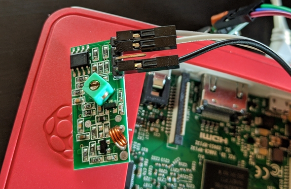
For the receiver, I've hooked the black wire up to the power, the white wire to the right data output, and the gray wire to the ground.
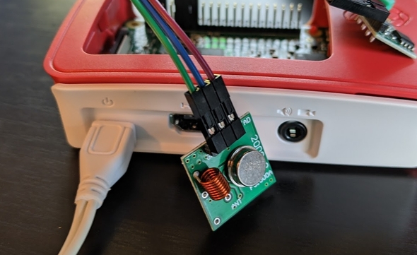
The transmitter has the purple wire connected to the data, the blue wire to the power, and the green wire to the ground.
Now, the hard part: getting everything attached to the Raspberry Pi GPIO pins. Again, if you use a breadboard, this is a bit easier, but I attached everything directly.
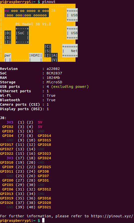
You can find a schematic of the Raspberry Pi GPIO pins on the official documentation site or pinout.xyz. You can also get a printout by running pinout on a terminal window on your Pi.
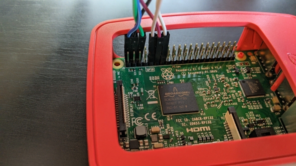
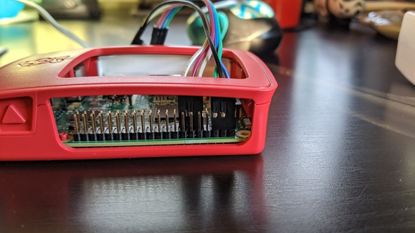
Here's what the connected components look like, from the top and the side of the GPIO pins.
I've plugged the blue wire into pin 2, the 5V pin, and the black wire into pin 4, another 5V pin, to provide power to both components. The green wire, the ground wire for the transmitter, is plugged into pin 6.
The gray wire, the ground wire for the receiver, is plugged into pin 9. The purple wire is plugged into pin 11, which is GPIO17, and provides data to the transmitter. The white wire is connected to pin 13, which is GPIO27, and gets data from the receiver.
You can plug the components into any of the GPIO pins, but the script I'm about to use to receive and transmit the RF signals defaults to pin 11 for the transmitter and pin 13 for the receiver.
Sniffing the RF signals
The Instructables tutorial teaches you how to create a script to use RPi.GPIO to sniff the signals given off by the remote, but I wanted something that would give me instant results. I'll eventually go back and create my own scripts as I work on other remote-controlled devices in the house.
This tutorial uses rpi-rf, which for some reason I couldn't get to work.
Looking around, I found rpi-rfsniffer which worked great for what I wanted to do. I installed the package with pip per the instructions and used the CLI to sniff my first signal.
rfsniffer record officefan.button1After a few seconds, the script returns how many transitions it's recorded. Then, I'd test the recording with
rfsniffer play officefan.button1Each recording took a couple of tries to get right. I have five buttons on this remote, and none of them worked correctly the first time. However, after a couple of tries receiving and transmitting, I had every button press recorded.
Note: I've read that having the receiver on the 5V pin can introduce noise to the recording. I actually had the power on the 3v3 pin when I did the recording the first time around. I had to hold the remote right up to the receiver, and it was recording very weakly. That's why I suggest trying the 5V pin first, but if it's recording too many bits of noise, try using one of the 3v3 pins for power.
A bare-bones web interface
Finally, to have a way to control everything from my phone instead of the command line, I needed to make a PHP file with some buttons that would send a POST request and execute the command. It's a relatively small file, with just one function.
<?php
function fanCommand($button) {
	exec('rfsniffer play officefan.' . $button);
}

if (isset($_POST['command'])) {
	fanCommand($_POST['command']);
}
?>

<!DOCTYPE html>
<html>
	<head>
		<title>Fan Controller</title>
		<meta name="viewport" content="width=device-width, initial-scale=1">
		<style>
			body {
				text-align: center;
			}
			input {
				width: 150px;
				height: 150px;
				border-radius: 5px;
				background-color: #dddddd;
				margin: 10px;
				padding: 10px;
				line-height: 5.5em;
			}
		</style>
	</head>
	<body>
		<form action="index.php" method="post">
			<input type="submit" name="command" value="button0" />
			<input type="submit" name="command" value="button1" />
			<input type="submit" name="command" value="button2" />
			<input type="submit" name="command" value="button3" />
			<input type="submit" name="command" value="light" />
		</form>
	</body>
</html>
It's just some HTML with a form and five buttons that posts to itself, and if a command is posted, it executes the command for the corresponding button. Very simple, nothing flashy.
I tested out the server with PHP's built-in web server.
php -S 192.168.0.47:8000After visiting 192.168.0.47:8000 on my phone, I could see that the page was working, and my fan would start, change speeds, and turn the light off and on. I'm not leaving this running for long, since it's very fragile, but it's a proof of concept!
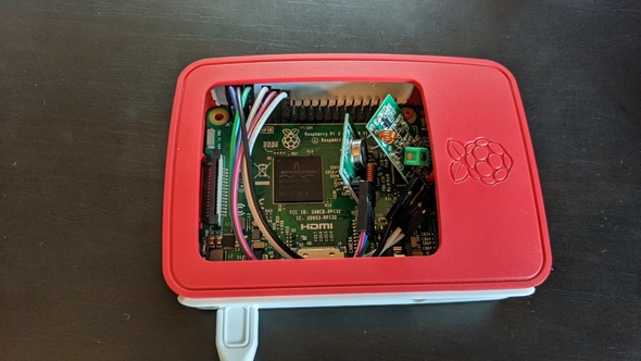
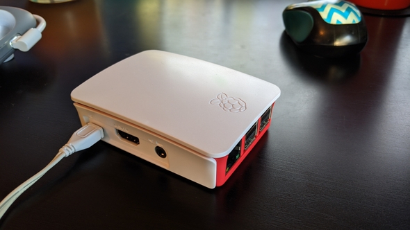
Finally, I very gently put both components inside the case and put the lid on. Maybe this is a horrible idea, I don't know, but I do like that it looks nice without wires everywhere. It still works, so at least for now, that's how it's going to be.
Once I'm done with the receiver I'll take it off the GPIO pins and just have the transmitter in there, but I still have another fan and a remote-controlled bed to try this on.
While I'd rather have something a little more polished and less fragile, this wasn't too bad for less than two hours of work!
